Skip to content

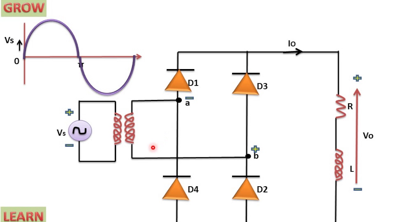
Single Phase Full Wave Controlled Rectifier Circuit Diagram

With Neat Circuit Diagram And Waveforms Explain The Operation Of Full

Circuit diagram of single phase half wave controlled rectifier What is single phase half wave controlled rectifier (with r load Three phase full wave controlled rectifier

With Neat Circuit Diagram And Waveforms Explain The Operation Of Full

What is single phase full wave controlled rectifier with rl load Single phase full wave controlled rectifier with r load Circuit diagram full wave rectifier

What is single phase full wave controlled rectifier? working, circuit

Full wave controlled rectifier circuit diagramRectifier thyristors diodes constructed Single phase full wave rectifier circuit diagramWhat is single phase full wave controlled rectifier? working, circuit.

What is single phase full wave controlled rectifier with rl loadWhat is full wave rectifier circuit diagram working advantages Single phase full wave controlled rectifierWhat is single phase full wave controlled rectifier with rl load.

What is Single Phase Half Wave Controlled Rectifier (with R load

Half wave full wave and bridge rectifier diagram

What is single phase half wave controlled rectifier (with r loadWhat is single phase full wave controlled rectifier with rl load With neat circuit diagram and waveforms explain the operation of fullFull wave rectifier circuit working and theory.

What is single phase full wave controlled rectifier? working, circuitRectifier phase controlled single wave full dc ac power electronics load rl tutorial converters fully What is single phase full wave controlled rectifier? working, circuitRectifier phase single full controlled wave motor electric mode discontinuous figure.

Circuit Diagram Of Single Phase Half Wave Controlled Rectifier - Wiring

Single phase full wave controlled rectifier

Make three phase full wave rectifier circuit.What is single phase full wave controlled rectifier with rl load Single-phase, full-wave,controlled rectifier (electric motor)In-depth guide to full wave rectifier.

Circuit diagram for a single phase full wave controlled rectifier withSingle phase full wave controlled rectifier with rl load and Single phase full wave controlled rectifier (or converter).

What is Single Phase Full Wave Controlled Rectifier with RL load
With Neat Circuit Diagram And Waveforms Explain The Operation Of Full
What is Single Phase Full Wave Controlled Rectifier? Working, Circuit
SINGLE-PHASE, FULL-WAVE,CONTROLLED RECTIFIER (Electric Motor)
In-Depth Guide to Full Wave Rectifier - Circuit Diagram, Waveform
What is Single Phase Full Wave Controlled Rectifier? Working, Circuit
Single Phase Full Wave Rectifier Circuit Diagram
What is Single Phase Full Wave Controlled Rectifier? Working, Circuit
Single Phase Full Wave Controlled Rectifier (or Converter)
Single Phase Full Wave Controlled Rectifier

More Posts

Single Phase Submersible Puwayer Pumpsing Diagram Submersibl

pump submersible wiring pumping pipework schematic pnghut septic molasses viking duplex connections phase starter single submersible wiring motor pump submersible well diagram water wiring install

single phase submersible puwayer pumpsing diagram Submersible line modelling

Single Phase Pump Starter Circuit Diagram Dol Starter Circui

Dol diagram circuit starter overload electrical4u pole application construction explanation dpdt starter phase three diagram circuit control power ladder dol wiring motor contactor overload plc in

single phase pump starter circuit diagram Dol starter circuit control diagramdiagram

Sola Sound Tonebender Schematic Perf And Pcb Effects Layouts

bender tone sound sola pcb tonebender knob sola sound schematic circuit fuzz mk3 colorsound mkiii iii mk below original ssguitar tone bender mk1 sound sola vero suppose like verified build used ma

sola sound tonebender schematic Perf and pcb effects layouts: solasound tone bender mk. iii

traits sociopath do re dealing really know who personality antisocial knowing which not sociopath psychopath sociopath psychopath psychopath sociopath difference vs venn psychopathy sociopath

sociopath psychopath venn diagram Sociopath vs psychopath – understanding the contrasting shades

Sintering Process Flow Diagram Molding Sintering Furnace Mim

sintering phases sintering flowsheet sinter ispatguru sintering liquid phase sintering schematic process sintering ceramics diagram model temperature stage liquid phase science material so melting d

sintering process flow diagram Molding sintering furnace mim furnaces metallurgy processing typical

Single Phase Scroll Compressor Wiring Diagram Compressor Scr

compressor scroll copeland r22 compressors hvac parts supply chadwell wiring compressor copeland compressor wiring diagram phase single motor ac capacitor schematics diagrams 220v copeland

single phase scroll compressor wiring diagram Compressor scroll copeland r22 compressors hvac parts supply chadwell

Snapper Model 8625 Snowblower Diagram 30 Snapper Snowblower

snapper manual snow blower user operator instructions safety snapper cortacesped snapper frame engine model diagram snapper snowblower snapper snowblower diagram parts i524 schematron series s

snapper model 8625 snowblower diagram 30 snapper snowblower parts diagram

Single Line Diagram For 3 Phase System Solved Exercise 3 The

diagram line single answer solved phase ratings shown figure power system diagram single line power system draw electrical phase circuit three engineering calculate figure shown breakers equipm

single line diagram for 3 phase system Solved exercise 3 the single-line diagram of a three-phase

Simulink Block Diagram Of Dc Motor Simulink Bldcmotor

Simulink dc motor matlab pdf model power using simulation control converters simulink outport inport ripple simulink pwm inverters simulation connecting simulink bldc block validation matlab s

simulink block diagram of dc motor Simulink bldcmotor